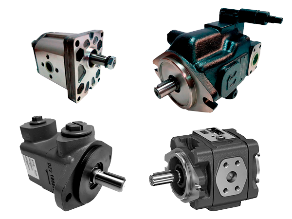
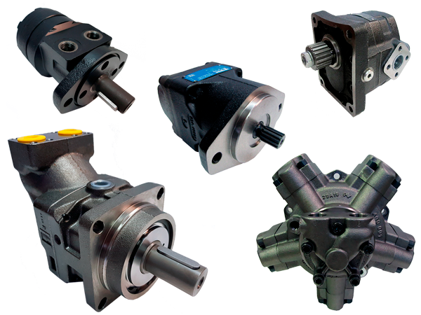
Fluid circuit diagrams are made by hydraulic symbols of components like cylinders, motors, pumps, valves, heat exchangers, filters, etc. connecting each other by means of pipelines, hydraulic manifolds or rigid tubes.
The organization ISO (International Standards Organization) by means of standard ISO 1219-1:2012 has defined the hydraulic symbols with the aim of a hydraulic circuit diagram can be understood by any technician with knowledge about hydraulics.

Below you will see some of the most common hydraulic schematic symbols used in a hydraulic circuit. Here you can also download hydraulic symbols in pdf or image that you may need:
Table of contents
- Hydraulic pump symbols.
- Hydraulic motor symbols.
- Hydraulic cylinder symbols.
- Hydraulic valve symbols.
- Hydraulic pressure control valve symbols.
- Hydraulic flow control valve symbols.
- Hydraulic check valve symbols.
- Hydraulic directional control valve symbols.
- Electric motors and Internal Combustion Engines elements symbols.
- Hydraulic connections and lines symbols.
- Hydraulic accessories symbols.
Hydraulic pump symbols
Unidirectional fixed displacement hydraulic pump symbol.

Bidirectional fixed displacement hydraulic pump symbol.

Unidirectional variable displacement hydraulic pump symbol.

Bidirectional variable displacement hydraulic pump symbol.

Hydraulic hand pump symbol.

CLICK HERE for more technical information about hydraulic pumps

Hydraulic motor symbols
Unidirectional fixed displacement hydraulic motor symbol.

Bidirectional fixed displacement hydraulic motor symbol.

Unidirectional variable displacement hydraulic motor symbol.

Bidirectional variable displacement hydraulic motor symbol.

Hydraulic rotary actuator symbol.

CLICK HERE for more technical information about hydraulic motors

Hydraulic cylinder symbols
Single-acting cylinder return stroke by external force symbol.

Single-acting cylinder return stroke through a spring symbol.

Double-acting cylinder symbol.

Double-acting cylinder with double rod symbol.

Double-acting cylinder with cushioning on one side symbol.

Double-acting cylinder with cushioning on both sides symbol.

Double-acting cylinder with adjustable stroke and cushioning on one side symbol.

Double-acting cylinder with adjustable stroke and cushioning on both sides symbol.

Telescopic cylinder single-acting symbol.

Telescopic cylinder double-acting symbol.

Hydraulic valve symbols
Hydraulic pressure control valve symbols
Hydraulic pressure relief valve direct operated symbol.

Hydraulic pressure relief valve pilot operated symbol.

Hydraulic pressure reducing valve direct operated symbol.

Hydraulic pressure reducing valve pilot operated symbol.

Hydraulic pressure sequence valve direct operated symbol.

Hydraulic pressure sequence valve pilot operated symbol.

Hydraulic counterpressure overcenter valve symbol.

Hydraulic flow control valve symbols
Hydraulic flow control variable throttling two way valve symbol.

Hydraulic flow control variable throttling with check valve symbol.

Hydraulic compensated flow regulator two-way valve symbol.

Hydraulic compensated flow regulator three-way valve symbol.

Hydraulic check valve symbols
Hydraulic check valve without spring symbol.

Hydraulic calibrated check valve symbol.

Hydraulic pilot operated check valve symbol.

Hydraulic pilot operated check valve with drainage symbol.

Hydraulic directional control valve symbols
Hydraulic directional control valve 2 ways - 2 positions symbol.

Hydraulic directional control valve 3 ways - 2 positions symbol.

Hydraulic directional control valve 4 ways - 2 positions symbol.

Hydraulic directional control valve 4 ways - 3 positions symbol.

Actuators for directional control valve symbols
Detent actuator for directional control valve symbol.

Pushbutton actuator for directional control valve symbol.

Lever actuator for directional control valve symbol.

Adjustable stroke actuator for directional control valve symbol.

Spring actuator for directional control valve symbol.

Cam actuator for directional control valve symbol.

Pneumatic actuator for directional control valve symbol.

Electric actuator for directional control valve symbol.

Proportional electric actuator for directional control valve symbol.

Hydraulic actuator for directional control valve symbol.

Electro-hydraulic actuator for directional control valve symbol.

Proportional electro-hydraulic actuator for directional control valve symbol.

Electric motors and Internal Combustion Engines elements symbols.
Electric motor symbol.

Engine motor symbol.

Rotary shaft in one direction symbol.

Rotary shaft in both directions symbol.

Hydraulic connections and lines symbols.
Main line symbol.

Pilot line symbol.

Drain line symbol.

Line pipe with flexible hose symbol.

Crossing lines symbol.

Connection point symbol.

Branching closed symbol.

Branching with connected piping symbol.

Fast coupling (or Quick coupling) symbol.

Fast coupling with check valves symbol.

Hydraulic accessories symbols
Hydraulic accumulator symbol.

Filter symbol.

Heat exchanger (heater) symbol.
 symbol.jpg)
Heat exchanger (cooler) symbol.
 symbol.jpg)
Heat exchanger (liquid operated cooler) symbol.
 symbol.jpg)
Reservoir (pipings above level) symbol.
 symbol.jpg)
Reservoir (pipings under level) symbol.
 symbol.jpg)
Pressurized reservoir symbol.

Pressure gauge symbol.

Differential pressure gauge symbol.

Pressure switch symbol.

Flowmeter symbol.

Maintenance, implementation or design hydraulic circuits require to understand schematics. In this blog you will find the basic vocabulary that you will need to work on a daily basis.
Date: 2022-11-03 21:30:00

SHIPPING WORLDWIDE
We help you to select the suitable hydraulic component for your machine or your new project. We can make urgent shipments to Anywhere in the World through leading logistics companies: DHL, TNT, Fedex, UPS, etc.


